-40%
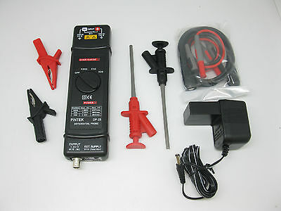
AideTek Pro Differential probes DC 25Mhz Max Voltage 1300V OEM Taiwan CAT3
$ 137.06
- Description
- Size Guide
Description
AideTek Pro Differential probes DC 25Mhz Max Voltage 1300V OEM Taiwan CAT3Description
New Professional
Differential
probes DC-25Mhz ADP25 Max Voltage 1300V or 1000V RMS
Brand new with 14 days return policy, one year warranty
3 RANGE ATTENUATOR.
1000V INPUT CAT III
LOW BATT. AUTO OFF.
SEPARATING DESIGN.CONVENIENT, DURABLE.
MEET CE, IEC 1010, EN 61010, UL 3111.
Band width (-3dB, 50Ω
load):
DC-25MHz . ( x 20: DC~15MHz)
Accuracy :
± 2% at 20-30℃ 70% RH after 20 minutes warm up.
Attenuation :
x 20, x 50, x 200 ( Into 1MΩ scope ) ; x 40, x 10
, x 400 ( Into 50Ω load )
Maximum operation Voltage ( DC + peak AC ) :
≦ ± 140V at x 20
≦ ± 350V at x 50
≦ ± 1300V at x 200
Maximum input Differential Voltage :
1300V ( DC + peak AC ) or 1000V RMS
Maximum input Voltage to Ground :
1000V ( DC + peak AC ) or 600V RMS
Common Mode Rejection Ratio ( CMRR ):
60Hz :
>10,000 : 1
100Hz:
>1,000 : 1
1MHz:
> 300 : 1
Noise :
≦ 2 mV rms ( Into 50Ω load )
Input Impedance :
2MΩ, 2.3 PF between inputs and ground.
4MΩ, 1.2 PF between inputs.
Power :
external 6V-9V DC
.
WARNING
Do not use DP-25 above 1000v ( DC + peak AC ) between ground and the input or 1,300V ( DC + peak AC ) between the input lead.
Do not operate DP-25 in wet or damp condition.
Do not operate DP-25 in an explosive atmosphere.
Do not immerse DP-25 in liquids.
Do not operated DP-25 without covers.
Please change the battery when the "LOW BATT " LED is lighted. At this time DP-25 can operate but not guaranteed the accuracy.
DP-25 can not operate if both POWER and LOW BATT LED are not light.
FEATURES
The DP-25 FET input differential probe provieds a safe means of measuring circuits with floating potentials up to 1000 V ( DC+ peak AC ) from ground and 1300V ( DC + peak AC ) differential.
The DP-25 converts the high voltage differencial input signal to a low voltage ground refereced signal for display on any Oscilloscope.
The output BNC of DP-25 is calibrted to drive a high impedance ( 1M
Ω
) load.
INSTRUCTION FOR USE
Connect the output BNC of DP-25 to the input BNC of the Oscilloscope by the accessory BNC cable.
Adjust the vertical offset of the Oscilloscope if necessary.
Set the select proper range of the DP-25 and the V / DIV of the Oscilloscope according to the scale conversion chart.
Scale conversion chart : The effective V / DIV is the attenuation factor of x 20, x 50, x 200 multiplied by the scale factor of the Oscilloscope. It will be twice when the 50
Ω
load was used. For example, with the range set at x 200,
and the scope set to 0.5 V / DIV, the effective V / DIV equals 200 x 0.5 or 100 V, with the 50
Ω
load was used, it becomes 200V, the power consumption will increase too.
NOTE :
If the voltage of the input signal exceeeds the linear range of the setting range.The signal output of the DP-25 would not accurately, the wave form display will be cut off.
Shipping ALL orders will ship from our China warehouse by air mail with track number, it takes around 7-12 business days to arrive, the track number will e-mail to you, thank you
This is manual:
http://www.aidetek.com/New_products_info/Datasheet/Pintek/A
DP25
_Manual.pdf
eBay Cross Border Trade powered by Channel Effect
